K2+ Software
Specifications and Optional Software
SINE
-
-
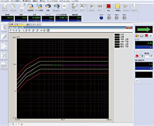
Specifcations Control Algorithm Continuous closed-loop control of true rms level Control Frequency Range 0.1 – 20000 Hz Control Dynamic Range More than 120 dB Operation Modes 1. Continuous sweep, Spot, Manual
2. Closed-loop, Open-loopMeasurement Method Average, RMS, Tracking Multiple-Channel Control Modes Average control, Maximum control, Minimum control Input Channels Maximum 20 *Specifications may be affected by other conditions
Optional Software
R_DWELL: Resonance Dwell
Resonance is detected by measuring the phase difference between the control point and the response signal from a resonant part of the item under test. The test frequency is controlled in order to maintain resonance as the structure fatigues. After holding at the resonance for a pre-defined duration, sweeping can be resumed until the next resonance is detected.
A_DWELL: Amplitude Dwell
A transmissibility plot is taken from two points on the structure under test and resonances listed. A sine test can then be run at each resonant frequency, with tracking of the resonance by either amplitude or phase.
LIMIT CONTROL
Response channels can be specified as limit control channels. If the level on a limit control channel is likely to exceed its limit, the test level is reduced accordingly.
Multi Sweep Sine
A traditional wide-band sine sweep is divided into several narrower-band sine sweeps, which when added together combine to cover the original wide band. Running the narrow band sweeps in parallel significantly reduces the test time required.
RANDOM
-
-
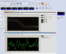
Specifcations Control Algorithm Closed-loop control of PSD within each spectral line Control Frequency Range 20 kHz maximum Number of Control Lines Maximum 25600 lines Control Dynamic Range More than 98 dB Loop Time 200 ms (fmas=2000 Hz, at L=400 line) Multiple-Channel Control Modes Average control, Maximum control, Minimum control Input Channels Maximum 20 *Specifications may be affected by other conditions
Optional Software
SOR: Sine on Random
An SOR test is a vibration test composed by adding random vibration to sine vibration simultaneously. It is possible for sine vibration to be swept in this test.
ROR: Random on Random)
An ROR test is a vibration test composed by superimposing a stationary broadband random vibration with a narrow band random vibration that is swept according to given sweep conditions.
EXTENDED ROR
The extended ROR makes it possible to execute an ROR test with greater freedom when defining separate NBR references.
PSD LIMIT: PSD limit control
Response channels can be specified as limit control channels. If the PSD on a limit control channel is likely to exceed its limit, the test level is reduced over that range of frequencies to keep within the limit level.
Non-Gaussian
A vibration testing method which precisely reproduces non-Gaussian vibrations, for example transportation vibrations, with largespikes.
Soft-Clippin
A clipping function that can reduce the peak value of the output voltage without affecting control performance.
SHOCK
-
-
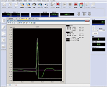
Specifcations Control Algorithm Finite-length waveform controlled by feed forward method Control Frequency Range Maximum 20000 Hz Number of Control Lines Maximum 25600 lines Control Dynamic Range More than 98 dB Type of Reference Waveform Classical shock waveform
(Half-sine, Haversine, Saw-tooth, Triangle, Trapezoid etc.),
Sine beat waveform, Measured waveform etc.Input Channels Maximum 20 *Specifications may be affected by other conditions
Optional Software
LONG WAVEFORM
The standard length of a reference waveform is 16 K points. This can be increased to 200 K points by adding the LONG WAVEFORM option. At a sampling frequency of 512 Hz for example, this produces approximately 6.5 minutes of waveform, compared to the standard length of approximately 30 seconds.
MEGAPOINT
A further increase in waveform duration can be obtained by adding the MEGAPOINT option to the LONG WAVEFORM option. This increases the record length to 5000K points, about 163 minutes at 512-Hz sampling rate.
SRS: Shock Response Spectrum
SRS (Shock Response Spectrum) can execute a test in which the test condition and evaluation are conducted not based on the waveform itself, but on SRS analysis. With standard shock test selected, SRS analysis of the response waveform is also possible.
Multi SINE
-
-
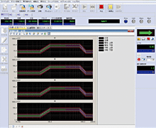
Specifcations Control Algorithm 1. Amplitude: Continuous closed-loop control of true rms level
2. Phase: Real-time waveform controlled by feed forward method
3. Monitoring and minimising of cross-axis componentControl Frequency Range 0.1 – 10,000 Hz Frequency Resolution Better than 10-4 of frequency Control Dynamic Range More than 120 dB Operation Modes 1. Continuous sweep, Spot test
2. Control and monitoring in various physical unitsEstimation Method Average, RMS, Tracking Multiple-Channel Control Modes Average control, Maximum control, Minimum control Input Channels Maximum 20 chs for principal control channel Output Channel Maximum 12 *Specifications may be affected by other conditions
Optional Software
LIMIT CONTROL
If a response point is specified to be a limit control channel, the level of that response point will not exceed the level specified in the test.
Multi RANDOM
-
-
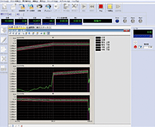
Specifcations Control Algorithm 1. PSD of random signal closed loop control by spectrum density for each frequency segment
2. Real-time waveform controlled by feed forward method
3. Monitoring and minimising of cross-axis componentControl Frequency Range Maximum 10000 Hz Number of Control Lines Maximum 3200 lines Control Dynamic Range More than 98 dB Loop Time 450 ms
(3-input, 3-output control, 120 DOF, fmax = 2000 Hz, L=200 line cross-talk information averaging times = 8 times/loop)Multiple-Channel Control Modes Average control, Maximum control, Minimum control Input Channels Maximum 20 chs for principal control channel Output Channel Maximum 12 *Specifications may be affected by other conditions
Optional Software
PSD LIMIT
Response channels can be specified as limit control channels. If the PSD on a limit control channel is likely to exceed its limit, the test level is reduced over that range of frequencies to keep with the limit level.
Non-Gaussian
A vibration testing method which precisely reproduces non-Gaussian vibrations, for example transportation vibrations, with large spikes.
Multi SHOCK
-
-
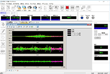
Specifcations Control Algorithm Finite-length waveform controlled by feed forward method Control Frequency Range Maximum 20000 Hz Number of Control Lines Maximum 25600 lines Control Dynamic Range More than 98 dB Type of Reference Waveform Classical shock waveform
(Half-sine, Haversine, Saw-tooth, Triangle, Trapezoid etc.),
Sine beat waveform, Measured waveform etc.Length of Reference Waveform Maximum 5000 k points Input Channels Maximum 20 Output Channel Maximum 12 *Specifications may be affected by other conditions
Optional Software
SRS: Shock Response Spectrum
SRS (Shock Response Spectrum) can execute a test in which the test condition and evaluation are conducted not based on the waveform itself, but on SRS analysis. With standard shock test selected, SRS analysis of the response waveform is also possible.

