
Vibration Test Systems/Vibration Shakers(FAQ)
Loop Check Errors Occur.
“Initialization failed” is displayed even though the wires are connected
If the tester and PC are all wired and
the tester, etc. are turned on and
the test definition is executed, the error
"Initialization failed. error is displayed and the test cannot be performed.
In most of these cases, the cause is one of the following two reasons.
(1) The controller is not turned on.
(2) The cable between the controller and the PC is loose.
Please check once again that the power is turned on and that the wires are securely connected.
Loop check errors occur
Reason:
(1) The changeover switch on the system controller has been changed.
(2) Sensor or low-noise cable is faulty.
(3) Wrong sensor settings.
Solution:
(1) Check the status of the changeover switch on the system controller.
Click here for details. What to do when a loop check error occurs (1)

(2) Replace the sensor or low noise cable.
Click here for details. What to do when a loop check error occurs (2)

(3) Check the sensor setting.
Click here for details. What to do when a loop check error occurs (3)
Power Amplifier Errors.
O.DISP error
Reason:
(1) The sensitivity of the sensor is wrong.
(2) The height of the vibration table is off-centre.
(3) Resonance between the vibration table and the shaker itself.
Solution:
(1) Check the sensitivity of the sensor.
(2) Check if the vibration table is in the middle when the power is turned on.
(3) <When it occurs during SINE test>
If it occurs at 10 Hz or lower, lock the body suspension.
However, use of the shaker with the body suspension locked will place a heavy load on the shaker and accelerate deterioration.
If the test continues beyond 10 Hz in a sweep test, press Pause when the frequency exceeds 10 Hz, unlock the body suspension with the shaker stopped, and resume the test.
Locking the body suspension during testing at frequencies above 10 Hz may cause the vibration to be transmitted significantly to the ground and in some cases may cause the shaker itself to move, resulting in a serious accident.
<If this occurs during RANDOM testing>
Lock the body suspension.
However, there is a possibility that the shaker itself may start to move, so increase the vibration level while observing the situation.
Locking the body suspension will place a heavy load on the shaker and accelerate deterioration.
The earth leakage detector works and the breaker trips.
Reason:
(1) The emergency stop button is being pressed.
(2) Poor insulation of the excitation coil
(3) Insulation failure of blower motor
(4) Insulation failure of transformer
Solution:
(1) Check that all emergency stop buttons are not pressed.
Click here for details. E.STOP causes and methods of investigation
(2) (3) (4) Check the timing when the leakage current detector is activated.
PM FLT error
Reason:
(1) Excessive testing.
(2) Power module is faulty.
Solution:
(1) Review the test conditions.
If within the ratings, check the sensitivity of the sensor, the mounting condition and whether the connectors are correctly connected.
(2) With the error occurring (before resetting), remove the front filter panel and check the position of the power module where the red LED is lit and what LED is lit from the left.
Check whether the amplifier panel fan is running.
Click here for details. PM.FLT causes and methods of investigation

FS FUS error
Reason.
(1) Fuse disconnection due to overcurrent in the excitation coil.
(2) Poor insulation of the excitation coil.
Solution.
(1) The fuse in the power amplifier (amplifier) may be broken.
(2) The excitation coil needs to be replaced.
O.HEAT error
Reason:.
(1) Blower is not working.
(2) The blower rotation direction is reversed.
(3) Duct hose is deformed, damaged or disconnected.
(4) The distance between the shaker and blower is too long.
(5) The temperature in the room is too high.
(6) The air supply or exhaust port of the shaker is blocked.
(7) Excitation coil is clogged with dust.
Solution.
(1) Check that the blower is working.
(2) Check if the blower is rotating in the correct direction (for direction of rotation, check the arrow near the blower motor).
(3) Check if the duct hose is not deformed, torn or disconnected.
(4) Check whether the length of the duct hose is within the allowable specification (5 m) of the IMV.
(5) Check whether the temperature inside the room is below 40°C.
(6) Check whether the air supply and exhaust ports of the shaker are free from blockages.
If there is a blockage, remove and clean the blockage.
(7) The shaker needs to be overhauled.
HPU error
Reason:
(1) Low oil pressure
(2) Low oil level due to oil leakage
(3) Abnormal tank upper limit
(4) Low primary water pressure (water-cooled hydraulic pressure source only)
Solution.
(1) Check the oil pressure
If the pressure is below the specified pressure, adjustment of the valve or repair of the hydraulic circuit (hydraulic hose, hydraulic pump, bearing, etc.) is required.
(2) Check the oil quantity
If the oil quantity is below the specified level, the oil needs to be replenished.
If the oil level continues to drop, the hydraulic circuit needs to be repaired.
(3) Check the oil level in the auxiliary tank under the horizontal auxiliary table and confirm that the pump is working.
(4) Check if the primary water valve for the hydraulic pressure source is open
Click here for details when there is a touch panel monitor. Concerning the hydraulic pressure source display monitor
H-E error
Reason:
(1) The secondary water temperature is above 40°C.
(2) Secondary water level is decreasing.
(3) Abnormal flow rate of primary water
(4) Abnormal secondary water flow rate
(5) Abnormal primary water pressure
(6) Leakage in the heat exchanger
(7) Leakage in the shaker
Solution:
(1) Check whether the cooling tower is operating normally and whether the primary water and secondary water valves are open.
(2) Check the amount of water in the tank and confirm that there is no water leakage from the water piping or shaker.
(3) Check whether the cooling tower is operating normally.
(4) Adjustment of the valve in the heat exchanger or replacement of the pump is required.
(5) Check whether the cooling tower is operating normally.
(6) Check if there is any water leakage inside the heat exchanger.
If there is water leakage, wipe it off and restart the machine. If it recurs immediately after restarting the machine, the heat exchanger parts need to be replaced.
(7) Check for water leakage from inside the shaker.
Click here for details when there is a touch panel monitor. Concerning the heat exchanger display monitor
THRY1 error
Reason: Thermal relay or thermostat actuation.
Solution.
Check whether the error can be reset by pressing and holding the reset button.
<If the error can be cleared>
The thermostat may be activated.
<If the error cannot be cancelled>
Several thermal relays may have tripped.
SUB2 error
Reason: Decrease in air pressure supplied to the shaker
Check items:
・If a compressor is included, make sure the compressor is turned on.
・Make sure the compressed air valve is open
・Check if the regulator pressure meter indicates the specified air pressure
*Please check the specified air pressure on the specification sheet or the label on the meter.
Click here for details. SUB2 causes and methods of investigation
L.VOLT error
Reason: Primary power supply voltage may be low.
Solution: Check the voltage of the primary power supply.
Click here for details. L.VOLT causes and methods of investigation

H.VOLT error
Reason: Primary power supply voltage may be high.
Solution: Check the voltage of the primary power supply
Click here for details. H.VOLT causes and methods of investigation

OSC.0 error
Reason:
(1) Input signal is received from the controller (K2) before the start of excitation.
(2) An input signal is received from an external device before the start of excitation.
Solution:
(1) Check whether the start of excitation of the controller (K2) is not pressed before the start of excitation.
(2) Check whether an input signal is input from an external device before start of excitation.
Click here for details. OSC.0 causes and methods of investigation
O.CURR error
Reason:
(1) Test conditions are not within the system rating.
(2) Mounting condition of the EUT.
(3) Sensor or low noise cable is faulty.
(4) Error in Sensor setting.
Solution:
(1) Check the test conditions. The upper limit value of acceleration varies depending on the mass of the EUT.
(2) Check that the EUT is not installed with extreme eccentricity.
(3) Replace the Sensor or low-noise cable.
(4) Check the Sensor setting.
Shaker Failure
Missing measurements due to cable disconnection of pickups occur.
Low-noise cables are always exposed to vibration and are therefore prone to wire breakage.
To prolong the life of the cable as much as possible, it is advisable to fix the cable to the jig or EUT with tape, etc. so that the cable does not get out of control during
testing.
When fixing the cable, please fix it so that the load is not applied near the acceleration pickup connector opening,
and that the wiring is not steep.
Noise from the blower
Reason:
(1) Motor characteristics.
(2) Blower is faulty.
Solution:
(1) The specifications of industrial motors have changed since 2015. Noise may occur with earlier blowers.
If the noise occurs in systems from 2015 onwards, measure the frequency of the noise.
If the noise appears around 2000 Hz or 4000 Hz, it is due to motor characteristics.
(2) Repair or replacement of the blower is required.
No excitation in horizontal position
Reason:
(1) The test piece is distorted.
(2) The shaker has not collapsed firmly.
(3) The pump is faulty.
(4) The joint attached to the shaker and the slip table are not aligned.
(5) The bearing of the slip table is faulty.
Solution:
(1) Remove the test piece and check if it can vibrate.
(2) When the vibratory apparatus is tilted horizontally, check whether the vibratory apparatus is tilted horizontally to the point where it hits the stopper.
(3) Check whether the pump under the slip table is running when the shaker is tilted horizontally and the breaker is switched on (power off).
(4) Install the joint, turn the shaker over horizontally and check that the bolts for connection go in smoothly.
(5) After checking (1) to (4), with the breaker switched on (power off), push the slip table by hand and check that it moves smoothly.
The table is elevated before the breaker is switched on.
Reason: Solenoid valve has failed
Solution: Check whether the shaking table is elevating with the circuit breaker switched off.
If it elevates, the solenoid valve must be replaced.
Noise from the shaker.
Reason:.
(1) Body suspension is not in the middle position.
(2) Mounting bolts for jig, sample and horizontal table are not all tightened.
(iii) The body is locked.
(iv) Mechanical failure of the shaker.
Solution.
①Adjust the body suspension to the middle position.
②Tighten all bolts.
(3) If body lock is not required, release it.
If body lock is required, review the test or review the testing machine.
(iv) Repair is required.
Errors in The Eco System (ISM)
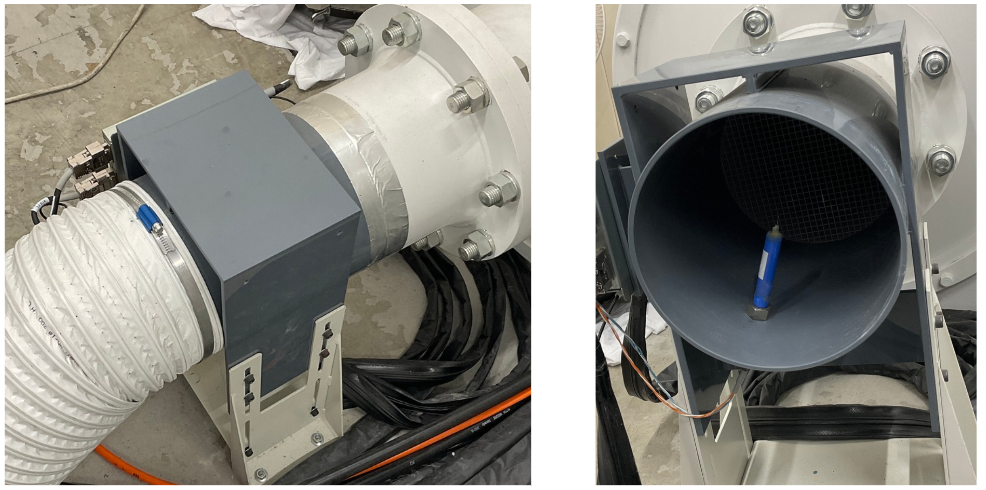
ISM airflow error
The following three potential causes may have triggered this error.
Please review and take the necessary actions:
1.Ducting Issues
Deformation or tears: The duct must be replaced.
Blockages: Remove any accumulated dust or foreign objects.
Disconnection: Reconnect the duct securely.
2.Dust Accumulation on Sensor
Gently clean the sensor with a soft brush to remove dust.
Note: Handle with care to avoid damaging the sensor.
3.Sensor Malfunction
The airflow sensor* requires replacement.
*Note: This refers to the sensor installed inside the relay duct section.
▼Sensor Location
ISM communication errors occur.
Reason: error due to wrong order of starting up PC and K2
Solution. Start up the PC and K2 before switching on the breaker of the power amplifier.
The power amplifier does not turn on when the button to start running K2 is pressed in the ISM
Reason: semi-automatic mode.
Solution:
(1) Check that the fully automatic mode of the ISM utility is enabled.
(2) Check that 'Use ISM' is checked in the ECO maintenance mode setting of the K2 option.
Want to know the ISM error code.
For units with ISM, press the power on button and it will switch off after approximately 3 minutes.
Possible causes:
Normal operation on devices with ISM when the power button is pressed manually.
Inspection items:
In fully automatic operation with ISM, it is not necessary to press the power on button (always do not press it)
When the circuit breaker is open, pressing the start-run button on K2 will automatically turn on the power
Vibration does not start.
Possible reason: semi-automatic mode
Solution:
・Check that the fully automatic mode of the ISM utility is enabled.
・Check that 'Use ISM' is checked in the ECO maintenance mode setting of the K2 options.
ISM cooling air system abnormal/Error ID 02
Reason:
(1) Abnormality of the duct.
(2) Dust has accumulated on the sensor attached to the relay duct.
(3) Failure of the air flow sensor.
Solution:
(1) If the duct is deformed or torn, it must be replaced.
In case of blockage, remove dust and other foreign matter
If disconnected, reconnect.
(2) Clean the sensor with a soft brush to remove dust.
Be careful not to damage the sensor.
(3) The air flow sensor needs to be replaced.
Vibration Controller (k2) Errors
Communication errors occur in K2.
Reason:. Abnormal communication between K2 and PC.
Solution. Disconnect the cable between K2 and the PC.
Exclamation mark appears and the start button cannot be pressed.
Reason: over-specified test settings
Solution:! mark to correct the test settings!
Stop at interruption checks.
Reason
(1) Sensor is disconnected.
(2) Sensor cable is disconnected or its sheath is broken.
(3) The sensitivity of the sensor is wrong.
Solution
(1) Check the condition of the sensor.
(2) Replace the sensor cable.
(3) Check the sensor sensitivity.
If the sensor sensitivity × acceleration exceeds 10000, change the sensor sensitivity from 10 mV/pC to 1 mV/pC.
K2 initialisation fails.
Reason:.
(1) K2 is not switched on.
(2) Poor communication between the K2 and the PC.
Solution:.
(1) Turn on the power to the K2.
(2) Restart the PC, unplug/plug the communication cable and restart the K2.
Error messages during the Shock test.
Error message
'The transfer function measurement was interrupted because the interruption level (upper and lower limit m/s2) of input channel xx was exceeded'.
Reason
The loop check signal has exceeded the interruption level.
Solution
Review the test definition
(1) Input channels → Select a control channel from the input channel arrangement and click Change.
Check Specify abort level and set a higher abort level (e.g. +300 m/s2 -300 m/s2).
(2) Check Specify initial output voltage for loop check from Vibration system settings and change the voltage to a smaller value (e.g. 30 mVrms→10 mVrms).
Computer Malfunction
PC won’t start up
Reason:.
(1) The computer is switched off.
(2) The computer is faulty.
Solution:.
(1) Turn on the computer.
(2) The PC needs to be repaired or updated.
The computer monitor does not work.
Reason:.
( i) The monitor's power supply is switched off.
( ii) The monitor is faulty.
(iii) Failure of the PC.
Solution:
( i ) Turn the monitor power supply ON.
( ii) The monitor needs to be updated.
( iii) The PC needs to be updated.
Chamber Errors.
Refrigeration machine abnormality occurs.
Reason: protection circuit in the refrigeration unit has been activated.
Solution: switch the appliance back on.
If the above does not improve the situation
Check the error code displayed on the refrigeration unit.
Abnormal discharge of cryocoolers.
Reason: increased R2 refrigeration discharge pressure
Solution: check the high pressure pressure of the R1 refrigeration unit in operation.
【Water cooling】
The adjusted value is 1.5 MPa.
If the pressure exceeds 1.5 MPa, clean the strainer, check the operation of the cooling tower and secure the water volume.
【Air cooling】
The adjusted value is 1.5 MPa. Compared to water cooling, it is more susceptible to outside temperatures.
If the high pressure always exceeds 2.0 MPa, use an air conditioner and keep the room temperature at around 20°C.
Alternatively, diffuse the exhaust heat from the refrigeration unit with a fan, or cool the R2 refrigeration unit with a spot cooler, etc.
If the above does not improve the situation
Spend the night with the unit ready for operation and check the high and low pressure of the R2 refrigeration unit.
If there is a significant change from the balance pressure attached to the unit, there is a possibility of refrigerant leakage.
(This is not a perfect match as it is affected by the ambient temperature.)
Terminology.
What is m^2/s^3 in the RANDOM test?
It is the power spectral density (m/s2)2/Hz.
Calculation formula:
Substitute Hz=1/s for power spectral density (m/s2)2/Hz
(m/s2)2/Hz
= (m2/s4)/Hz
Substituting Hz=1/s
= (m2/s4)/(1/s)
=m2/s3
Pickup failure
When accelerometer readings go wrong at low or high temperatures
Water contamination from the acceleration pickup connector port is a possible cause.
Waterproofing is required at the connector port when operating at temperature or when testing under conditions where condensation occurs.
Please refer to the instruction manual for the waterproofing method, which differs depending on the type of equipment.
Other
I lost my disk or forgot my password,so I can’t access my test history
We can retrieve your password and reissue your disc.
Please note that the installation disc is required when updating your PC, so we highly recommend keeping it on hand.
If you have the disc but have forgotten your password, you can find it in the "Password.txt" file located on Installation Disc (DISC1).