
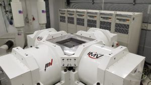
Aircraft parts 3D Testing
3D Testing on an Aircraft Main Landing Gear Bay Component.
Two customers have asked IMV to support their vibration testing with the scope to replicate the failure on a component installed in the landing bay on aircraft.
It has been discovered by the customer that some on the in-service airplanes have experienced wear to the components installed in the main landing gear bay.
Even if the failure is not compromising the safety of the aircraft and the passengers, the customers have decided to perform a vibration test campaign to define the root cause of the issue and define a design change to solve the issue.
To reproduce the vibration as much as possible like the one the airplane experience in its life, the customer has decided to perform the test on a 3D shaker, where all the 3 axes are excited simultaneously.
The test campaign has been scheduled from Monday the 20th of August 2018 till Friday the 24th of August.
They have asked to perform the following test profile with the shaker 3D to collect as much data as possible
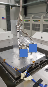
- As first test the they have requested to identify the resonance frequencies of the UUT (Unit Under Test) performing a resonance search in each axis separately.
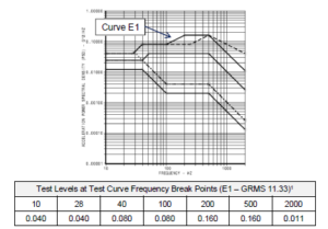
After this the most severe RTCA DO-160G, Section 8, Curve E1 performed on X, Y and Z simultaneously for a duration of three hours has been planned.
Before applying the profile, a tuning of the shaker system has been performed by the IMV team to understand the three-dimensional behaviour of the UUT on the shaker. After the tuning it has been decided to perform the test requested applied in each axis simultaneously with a reduction factor equal to 0.7 and due to the resonance of frequency of the fixture itself it has been decided to reduce the frequency range up to 800 Hz.
Once the test has been performed a second resonance sweep has been performed to check for a different behaviour of the UUT.
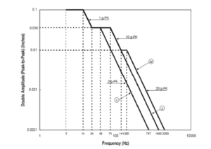
If the failure was not reproduced within the first 3 hours of testing it was planned to perform a single axis vibration using the RTCA DO-160G, Section 8, Curve W and a final resonance check.
After the first three hours of testing the UUT has been removed from the shaker and carefully inspected.
The inspection has shown clear wear signs and scratches on the components similar to the one find in the aircraft in service.
Confident and satisfied by the first testing results, different configurations have been tested during the week and each configuration has been inspected after the first 3hours testing.
They have discovered that the RTCA Do-160G, Section 8, Curve E1 profile reduced by 30% and applied simultaneously on the 3 axis was able to reproduce similar wear damages on all the tested configurations, with different level of wear to indicate the configuration was able to withstand better the vibration levels.
This type of failure is experience after 10.000 15.000 flight hours ( 3 – 5 years from the entry in service depending on the airline) and with the 3D shaker on 6 different configuration we were able to produce the damage and they recognise those damages as the root cause of the failure.
They were very happy by the results achieved and impressed by the 3D shaker system.
Currently the customers are reviewing and using the data collected during the testing week to upgrade the current design to withstand the flight loads.